

Description
The temperature sensor measures the temperature through a platinum thermistor installed in the probe tube. When the temperature changes, the platinum resistor outputs a resistance signal that changes with temperature through the connector. Through the characteristic of the platinum thermistor changing resistance value with temperature within the temperature range, the resistance signal at the measurement position is fed back to the corresponding system module for processing, converted into a temperature signal, and real-time monitoring of temperature changes at the testing position ensures the safety of train operation.
Structure
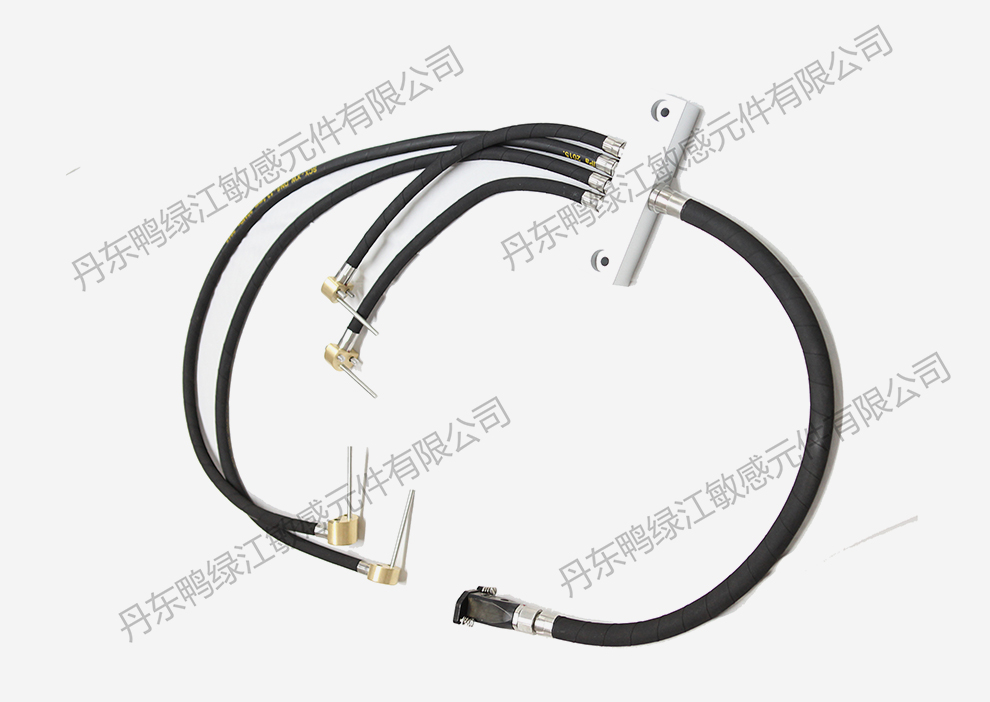
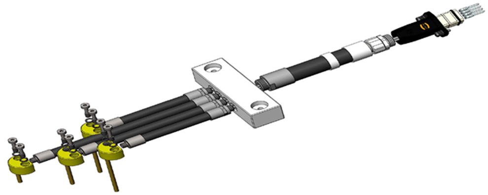
The gearbox temperature sensor is mainly composed of a probe component, a hub, an outer sheath component, and a connector. The specific structure is shown in the figure below. The probe component is a armored component of a platinum thermistor and cable, welded and formed by stainless steel protective tube and brass fixed shell to ensure tensile strength and airtightness. The sheath component is formed by crimping braided rubber tubes, joints, and sealing components, ensuring tensile strength and airtightness while effectively preventing the cable from being hit by external forces. The connector realizes the connection between the connector and the braided rubber hose.

Technical parameters
Technical parameters
| Graduation number | Measurement range | Detection current | Insulation resistance | Remarks |
| Pt100 | -50℃~200℃ | ≤1mA | DC1000V | Can be designed and manufactured according to customer requirements |
| ≥200MΩ |
Accuracy level
| Temperature | Class A | Class B | ||
| (℃) | ℃ | Ω | ℃ | Ω |
| 0 | ±0.15 | ±0.06 | ±0.3 | ±0.12 |
| 100 | ±0.35 | ±0.13 | ±0.8 | ±0.30 |
| 200 | ±0.55 | ±0.20 | ±1.3 | ±0.48 |
Matters needing attention
1. During installation, sensors and electrical connectors should be well protected, and it is strictly prohibited to fall or collide;
2. After the installation and connection of the sensor are completed, the wiring should be checked for correctness and confirmed before power can be transmitted to avoid damage caused by strong electricity mistakenly connecting to the sensor;
3. When the storage period of the sensor exceeds 1 year, the temperature resistance value and insulation resistance value of the sensor should be tested before installation to ensure good sensor performance;
4. The scrapped sensors should be properly disposed of to avoid any impact on the environment.


 QQ
QQ Speed-dial
 Follow WeChat